
Keypad library for Arduino
In this article I'll show you how to connect and use an Arduino UNO and a matrix type keypad. Also we are going to learn how to use a library for keypads named "Matrix Keypad library".
What is a keypad?
"A keypad is a set of buttons arranged in a block or "pad" which usually bear digits, symbols and usually a complete set of alphabetical letters."¹
There are different types of keypads, with numbers or letters, and also the size can vary from 3x4 to 4x4.
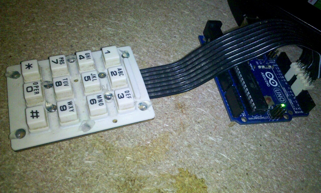
The keypad we are going to work with is the one in the picture:
- Size: 3x4
- Type: Numerical keypad
- It has 8 wires, from which we are going to use only 7 (we ignore the wire which connect the keypad to the keypad-board).
There are different types of keypads, with numbers or letters, and also the size can vary from 3x4 to 4x4.
The keypad we are going to work with is the one in the picture:
- Size: 3x4
- Type: Numerical keypad
- It has 8 wires, from which we are going to use only 7 (we ignore the wire which connect the keypad to the keypad-board).
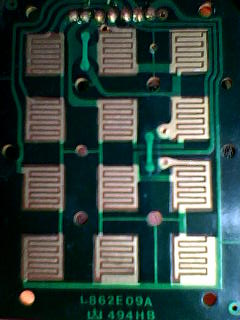
How does a keypad works?
The wire numbers 1 to 3 represents the columns and the next 4 wires represents the rows. From left to right.
Here are some examples:
- If you press the '1' button of the keypad, a connection is made between column 1 with row 1.
- If you press the '*' button, it will connect the column 1 (wire 1) with row 4 (wire 7).
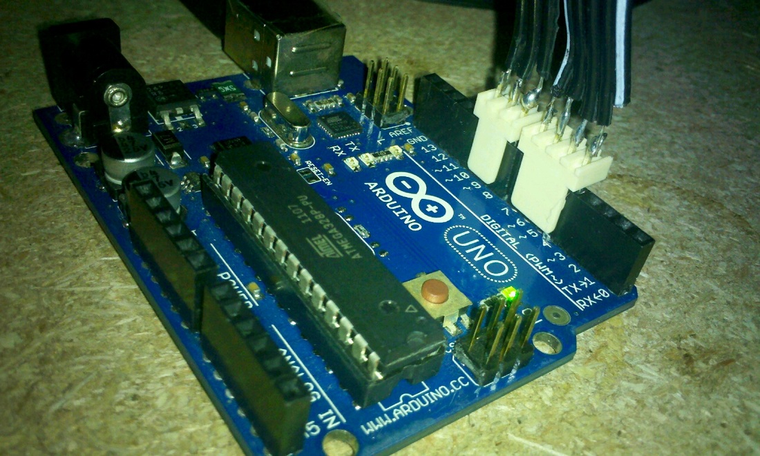
The next part is easy: connect the wires of the keypad to the digital pins of the arduino. We will explain this step later when we cover the library used to control the keypad.
The connection of the keypad wires to the arduino board is direct, without any additional component.
This is all we need to do about the hardware.
Keypad Library
The "Matrix Keypad library"² help us to use the keypad in an easier way. This library was created to promote Hardware Abstraction and it improves the readability of the code.
Download the Keypad library from here: http://arduino.cc/playground/uploads/Code/keypad.zip
Once you install it, we need to import it into the code:
#include<Keypad.h>
The next step is to define the number of columns and the number of rows:
const byte ROWS = 4; //four rows
const byte COLS = 3; //three columns
Then is necessary to specify the size and structure of our keypad. Notice that you should define this structure according to your keypad, in our case:
char keys[ROWS][COLS] = {
{'1','2','3'},
{'4','5','6'},
{'7','8','9'},
{'*','0','#'}
};
You can change the character of the matrix as you want. For example, you can change the '*' for a '\n' (newline character), then when you print into the serial port you'll see that a new line was printed instead of the '*'.
Now we define in which pin we have connected the keypad wires:
// Connect keypad ROW0, ROW1, ROW2 and ROW3 to these Arduino pins.
byte rowPins[ROWS] = {7, 6, 5, 4};
// Connect keypad COL0, COL1 and COL2 to these Arduino pins.
byte colPins[COLS] = {10, 9, 8};
We create a keypad object from the class Keypad that we found in the library:
Keypad kpd = Keypad( makeKeymap(keys), rowPins, colPins, ROWS, COLS );
Ready! You can use your keypad with your Arduino now!
Examples
Print the key pressed on the serial port:
#include <Keypad.h>
const byte ROWS = 4; //four rows
const byte COLS = 3; //three columns
char keys[ROWS][COLS] = {
{'1','2','3'},
{'4','5','6'},
{'7','8','9'},
{'#','0','*'}
};
byte rowPins[ROWS] = {5, 4, 3, 2}; //connect to the row pinouts of the keypad
byte colPins[COLS] = {8, 7, 6}; //connect to the column pinouts of the keypad
Keypad keypad = Keypad( makeKeymap(keys), rowPins, colPins, ROWS, COLS );
void setup(){
Serial.begin(9600);
}
void loop(){
char key = keypad.getKey();
if (key != NO_KEY){
Serial.println(key);
}
}
Login:
#include <Keypad.h>
#include <Password.h>
Password password = Password( "1234" );
int ledPin = 13;
const byte ROWS = 4; //four rows
const byte COLS = 3; //three columns
char keys[ROWS][COLS] = {
{'1','2','3'},
{'4','5','6'},
{'7','8','9'},
{'*','0','#'}
};
byte rowPins[ROWS] = {7, 6, 5, 4};
byte colPins[COLS] = {10, 9, 8};
Keypad keypad = Keypad( makeKeymap(keys), rowPins, colPins, ROWS, COLS );
void setup(){
Serial.begin(9600);
keypad.addEventListener(keypadEvent);
Serial.print("Type your password to enter!\n\n");
Serial.print("Pressed: ");
pinMode(ledPin,OUTPUT);
digitalWrite(ledPin,LOW);
}
void loop(){
keypad.getKey();
}
void keypadEvent(KeypadEvent eKey){
switch (keypad.getState()){
case PRESSED:
switch (eKey){
case '*': checkPassword(); break;
case '#': password.reset();Serial.print("\nPressed: ");break;
default: password.append(eKey); Serial.print(eKey);
}
}
}
void checkPassword(){
if (password.evaluate()){
Serial.println("\nSuccess!!!");
digitalWrite(ledPin,HIGH);
delay(4000);
digitalWrite(ledPin,LOW);
}else{
Serial.println("\n\nWrong password");
password.reset();
Serial.print("\nPressed: ");
}
}
As you can see in the second example, I used the "Password library"³, very useful for this case ;)
You can find all the information and examples, except for the last one in the references.
References
1- Keypad, http://en.wikipedia.org/wiki/Keypad, last accessed on 31 May 2012.
2- Keypad, http://arduino.cc/playground/Main/KeypadTutorial, last accessed on 31 May 2012.
3- Password library, http://arduino.cc/playground/Code/Password, last accessed on 31 May 2012.
4- Keypad library, http://arduino.cc/playground/Code/Keypad, last accessed on 31 May 2012.
Happy Hacking!!
2- Keypad, http://arduino.cc/playground/Main/KeypadTutorial, last accessed on 31 May 2012.
3- Password library, http://arduino.cc/playground/Code/Password, last accessed on 31 May 2012.
4- Keypad library, http://arduino.cc/playground/Code/Keypad, last accessed on 31 May 2012.
Happy Hacking!!
