
Toti the robot
This is Toti!
Introduction
Making robots and learn how to program them has been and it is the dream of a lot of young boys, hackers, researchers and a lot people in general. Being able to design and build your own robot seems to boost the imagination and creativity. Some robot build-your-self kits had been even sold in street newspapers kiosks with success and a lot of academic and non-academic work has been done in the field. New kits and peripherals, now cheap enough to be bough by most of people has also helped to bring this desire closer.
Nevertheless, building a robot still needs of microcontrolers to be programmed and electronic components to be understood, but even this complex subject is more and more accessible now a days. Programming languages are more intuitive than before, and new microcontrolers building-frameworks are available, making the building of a robot an achievable issue.
This work was born as a side-project of an information science engineer that wants to learn and build its own robot and also go deeper into the insights of microcontrolers programming. Having a strong background in computer programming and mechanical developments make it easier to understand and implement the ideas, resulting that after several months of study, testing and errors, the Toti robot was finished.
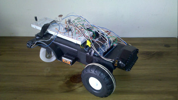
Toti, as it can be seen finished in Figure 1, was built upon the Arduino platform with the important premise of being as cheap as possible. We want to probe that using almost only recycled electronic components (like an old CD player) a cheap robot can be made at home. The complete list of Toti's features is:
Nevertheless, building a robot still needs of microcontrolers to be programmed and electronic components to be understood, but even this complex subject is more and more accessible now a days. Programming languages are more intuitive than before, and new microcontrolers building-frameworks are available, making the building of a robot an achievable issue.
This work was born as a side-project of an information science engineer that wants to learn and build its own robot and also go deeper into the insights of microcontrolers programming. Having a strong background in computer programming and mechanical developments make it easier to understand and implement the ideas, resulting that after several months of study, testing and errors, the Toti robot was finished.
Toti, as it can be seen finished in Figure 1, was built upon the Arduino platform with the important premise of being as cheap as possible. We want to probe that using almost only recycled electronic components (like an old CD player) a cheap robot can be made at home. The complete list of Toti's features is:
- Double independent front-motor powered traction.
- Object detection and avoidance in dark or light conditions.
- Ambient light sensing.
- Dynamic light threshold configuration.
- Start and stop button.
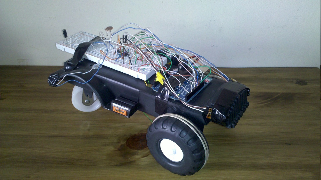
Figure 1
This paper goal is to show the building and development process of Toti, its mayor advantages and disadvantages, the designs decisions taken and the results achieved, hoping they will be of some help to other researchers.
Our main contributions are:
Our main contributions are:
- The design of a cheap and functional robot.
- The design of an object detection pulse-based algorithm.
Design
Toti's design can be described from both the mechanical/electronical point of view or the programming point of view. From the mechanical point of view Toti has a simple design, implementing only three wheels with two motors in the front. This may not be the most implemented and optimal configuration, but was useful enough to work fine. At the front it also has two infrared custom-made distance sensors which helps Toti to avoid objects and a light sensor to determine when to stop and hide in the dark.
From the programming point of view, Toti was developed using the Arduino User Interface, that makes it easy to control the different components and sensors. This interface gives also the opportunity to program the AtMega microcontroler with every low-level original primitives. At first we choose to use the Arduino Duemilanove open platform because of its simplicity, wide adoption, user base support and powerful capabilities. The Arduino has made it easy to create the robot. In the next subsections we are going to better describe every component of Toti.
From the programming point of view, Toti was developed using the Arduino User Interface, that makes it easy to control the different components and sensors. This interface gives also the opportunity to program the AtMega microcontroler with every low-level original primitives. At first we choose to use the Arduino Duemilanove open platform because of its simplicity, wide adoption, user base support and powerful capabilities. The Arduino has made it easy to create the robot. In the next subsections we are going to better describe every component of Toti.
Arduino
The Arduino platform (http://www.arduino.cc) was selected because of its easy of adoption, development and versatility. We are not going to talk long about Arduino in this paper, but some of the features that make us use it were:
• Uses FTDI chip for USB communication.
• Uses ATmega328 Microcontroller.
• Digital I/O Pins 14 (of which 6 provide PWM output).
• Analog Input Pins 6.
• DC Current per I/O Pin 40 mA.
• DC Current for 3.3V Pin 50 mA.
• Clock Speed 16 MHz.
• It is immensely popular and used as the core for many educational classes.
• It has both 3.3V and 5V regulated power supplies broken out.
• It has both USB and barrel jack ports for easy power, and communication.
• New to the Duemilanove is an auto power detection circuit. This will automatically select power from the barrel jack or USB.
• All pins are broken out to female headers for easy connections.SensorsPlaying with sensors was a really long and fun entertaiment.
We use several different distance sensors. The first tests were done using recycled mouse IR sensors, which worked fine but had a very short distance range.
Sensors
Usually, distance sensors are an expensive piece of equipment and not very easy to find sometimes. This limitation has lead us to experiment and create our own distance infrared sensors. Playing with sensors has been very entertaining and educational and shed light over many of the complex situations that we can find when building a robot. The first tests were done using recycled mouse IR sensors, which worked fine but had a very short distance range. After these experiments, we buy two infrared light led receivers and two infrared led transmitters to build some home made distance sensors. These sensors, as seen in Figure 2, were adjusted and tested until we found the correct way to position them and detect objects successfully. This leds were weld into a broken PCB board to avoid movement and a four-row connector was attached to their end, granting an easy assembly and disassembly.
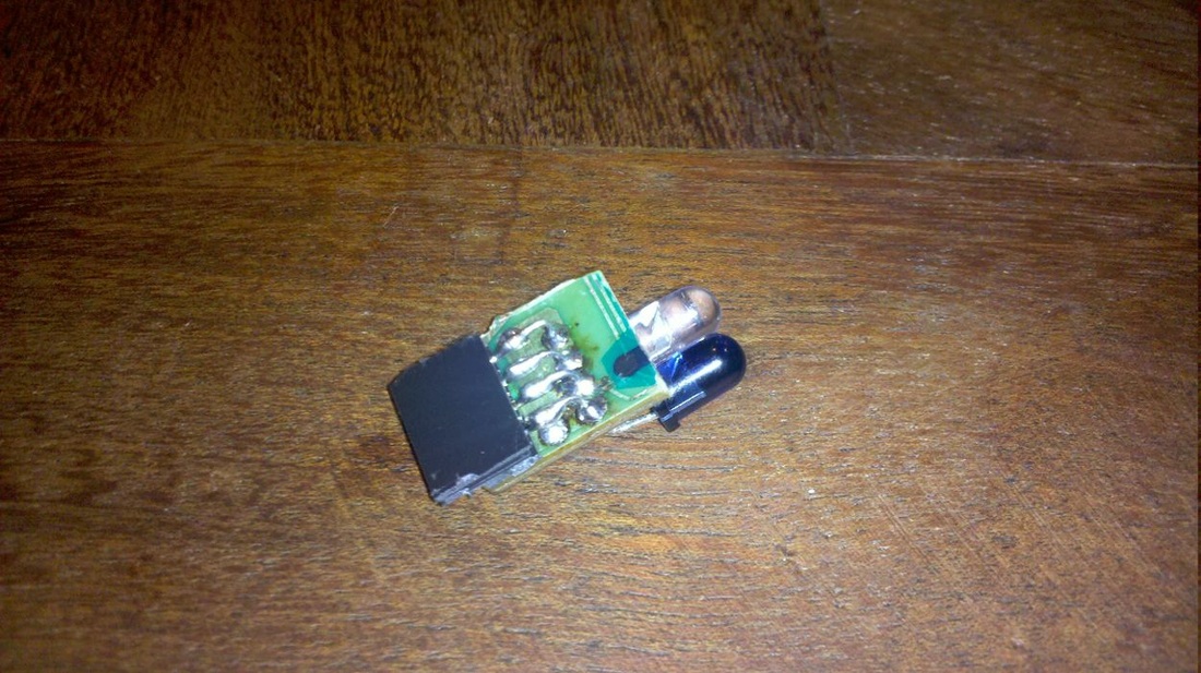
Figure 2
Object Detection
Our sensors does not have any internal logic or pre-programming capabilities, so we need to develop the detection logic in the main Arduino program. Object detection was designed to avoid objects in Toti's path, but multiple configurations were possible. Sensors were positioned 45 degree from Totis largest axis in order to detect objects near the wheels. When, in the first tests, sensors were positioned alongside (in parallel) with the largest Toti's axis, we were only able to detect objects going straight to the sensors. In Figure 3, we show how these sensors were calibrated to accomplish its task without problems. For example, in Figure 4, we can see that Toti is able to detect objects perfectly almost 17cm ahead and not fully in front of it. This was achieved mainly because of the use of 45 degree IR sensors and a proper configuration.
Thanks to José Marone advisory, we developed a detection algorithm which was configured to send and detect the reflection of an infrared (from now on IR) beam. The main idea is to generate IR pulses with a certain shape and to detect them with the IR receiver at the same moment. When no pulse is being generated, no pulse should to be detected with the sensor. This is the main reason of why we can detect objects with different light conditions and in the dark. AnFigure can be seen in Figure 5.
Thanks to José Marone advisory, we developed a detection algorithm which was configured to send and detect the reflection of an infrared (from now on IR) beam. The main idea is to generate IR pulses with a certain shape and to detect them with the IR receiver at the same moment. When no pulse is being generated, no pulse should to be detected with the sensor. This is the main reason of why we can detect objects with different light conditions and in the dark. AnFigure can be seen in Figure 5.
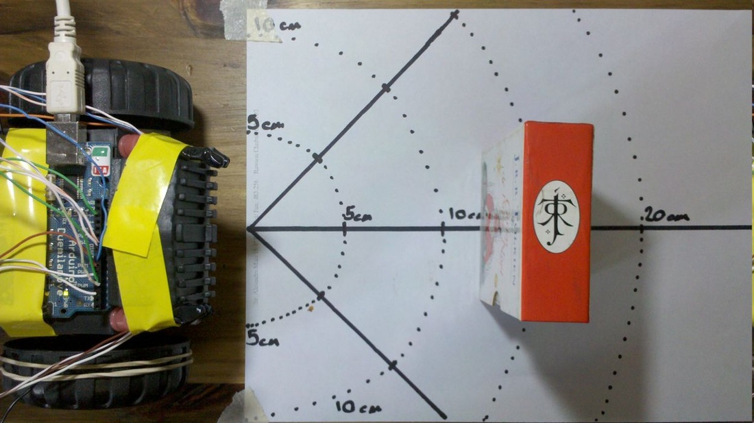
Figure 3
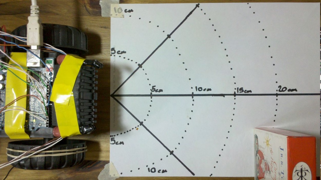
Figure 4
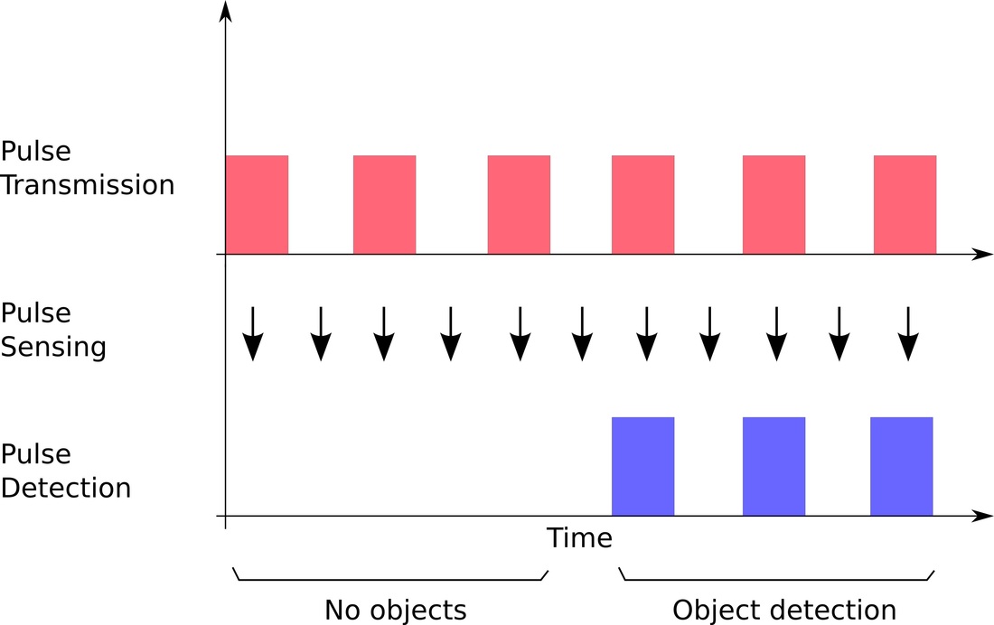
Figure 5
Light detection
Toti was equipped with an LDR light sensor to detect when it is under some light threshold value in order to stop working. The sensor was originally configured to work with a fixed value but this caused troubles when the environmental light characteristics change. To solve this issue, we reprogrammed the button functionality to enable a quick light threshold value configuration.
The new idea, was that before using Toti you could configure it on-the-fly to work under the light characteristics of the place where you are. To configure Toti dynamically, you must put it under the amount of light that you want to trigger the stop condition and quickly double press the start button. If everything goes right, the status led will blink twice and Toti will be ready to be used properly. This dynamic configuration of Toti empower the test of Toti under different circumstances.
The new idea, was that before using Toti you could configure it on-the-fly to work under the light characteristics of the place where you are. To configure Toti dynamically, you must put it under the amount of light that you want to trigger the stop condition and quickly double press the start button. If everything goes right, the status led will blink twice and Toti will be ready to be used properly. This dynamic configuration of Toti empower the test of Toti under different circumstances.
Start and Stop functions
To stop and start the robot, it was equipped with a recycled CD reader button. This button was placed at the rear of the robot and allows you to stop and start it properly.
Motors
When trying to design the traction base, we have the same problem of very expensive components as with sensors. It is very difficult to find small and cheap motors in the market, so we decided to reuse old CD players DC motors. These motors are very powerful and three of them can be found on every old CD player. We manage to control them using the PWM (pulse width modulation) techniques embedded in the Arduino. In Figure 6 we can see our first motor tests, trying to find out how was the optimal performance of it.
Motor's gear used in Toti were also the ones coming along with the motors in the CD players, because they were already designed to work properly. After a correct assembly, we can see in Figure 7, how the two main motors were put in place. This last part of the motor building was the most time consuming and difficult, because we have to literally completely build the whole schema.
Robot motors were controlled by an L293D H-bridge.
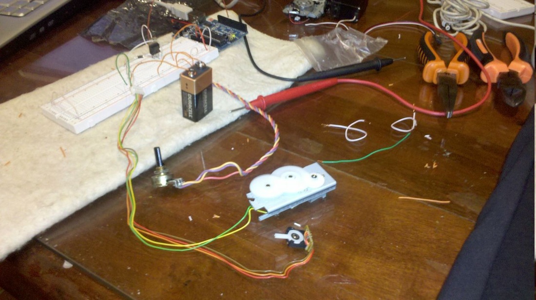
Figure 6
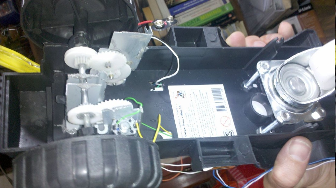
Figure 7
Building procedure
Toti connection schema was done with the Fritzing software (http://fritzing.org/), as can be seen in Figure 8, and it allowed us to clearly design, measure and think every aspect of it.
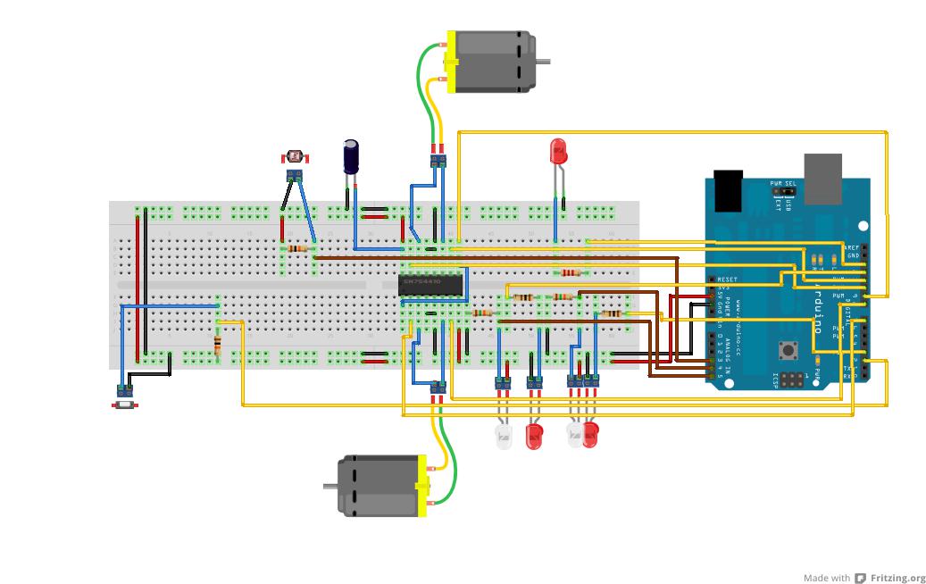
Figure 8
Toti was first build in a shoes box, until every test was finished. Once we knew which motors and sensors we were going to use, and that the program was executing correctly, we start to build the final Toti shape from a tractor toy's structure, as shown in Figure 9. From this base we create and assembly the motors, the sensors and the rest of the components.
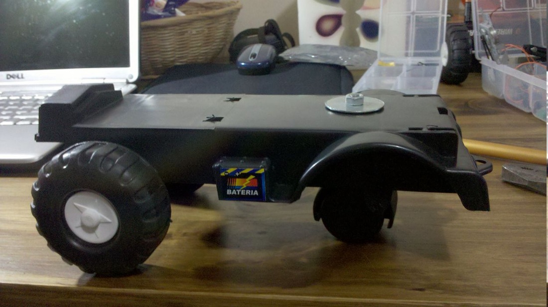
Figure 9
Total cost
Toti's build cost was approximately of U$S 55, including the Arduino Duemilanove, but our latest research about Arduino replacements has given us a new opportunity to lower the total cost of Toti to U$S41 welding our own Severino board (http://www.arduino.cc/en/Main/ArduinoBoardSerialSingleSided3).
Program
Arduino comes with a great user interface to correctly develop and program the AtMega microcontroler. The USB connection makes it really easy to develop, upload and test the improvements within seconds, speeding up the process.
The final Toti's program can be found at Arduino PDE program section. Development was done trying to create functions that could be reused later and easily modified using no external libraries except for the AVR include files. Most of the functionality was achieved using common Arduino's functions, but when we need to manage time interrupts correctly, we have to use AtMega's functions directly (i.e. ISR function)
The AtMega programming was quickly done mostly because of Arduino's capability of wrapping up the microcontroler functions. For example, when handling the digital outputs, we only need to assign the HIGH value using the digitalWrite function.
Testing
Toti was tested at every stage for errors and corrections. And several videos of these test can be seen online. The complete list of videos is:
- Toti was born: http://www.youtube.com/user/el2000draco#p/u/11/F_7-pWR3jZU
- Second test, one motor: http://www.youtube.com/user/el2000draco#p/u/10/-9bnMqFHg70
- Third test, one faster DC motor: http://www.youtube.com/user/el2000draco#p/u/9/73bsBmH0bQA
- Fourth test, DC motor speed control: http://www.youtube.com/user/el2000draco#p/u/8/B5hEAzHt7x4
- Toti has an eye using a mouse optical infrared sensor: http://www.youtube.com/user/el2000draco#p/u/7/1zriACR8kYY
- Toti with a distance sensor dodging objects: http://www.youtube.com/user/el2000draco#p/u/6/qMGdY0s7Rvo
- Toti is smarter, dodging objects with and without light: http://www.youtube.com/user/el2000draco#p/u/3/qu_qIJtRKS8
- Toti with two motors dodging objects: http://www.youtube.com/user/el2000draco#p/u/2/Dyvbyy-sdTY
- Toti with two motors, dodging objects with more control: http://www.youtube.com/watch?v=g_S219gpiJQ
- Toti using two DC motors, dodging objects with two sensors and sensing daylight to sleep: http://www.youtube.com/user/el2000draco#p/u/0/lX3ZSk9cZ40
- Added capacitors to add strength to the hardware design: http://www.youtube.com/user/el2000draco#p/a/u/0/4v82Kq66QBw
PCB construction
After several months of usage, Toti shows great stability and precision, allowing us to continue to the next phase of development. We started to design and build the final PCB board that will hold Toti's components from now on. In Figure 10 we can see the Fritzing design of this future PCB board, which was made to match exactly with the Arduino shield shape.
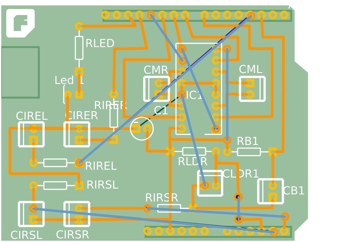
Figure 10
Conclusion
This project has been very educational to us, resulting in an entertained and useful experience. We were able to create and program a complete and functional robot with U$S 55, which was tested on several different environments. The Arduino platform was a key component that worked fine along the tests, even supporting some electrical misconfigurations. We want to thanks the MatesLab members and the teachers of the UNICEN University who have made possible the finalization of this project.
Files
| Building and programming an autonomous Robot - by Sebastián García.pdf |
| toti_v2_1.pde |
